
A thermal evaporation (TE) component typically consists of power supply rods, usually fashioned from thick copper, mounted to feedthroughs that allow transmission of current from an air-side power supply network through to a high-vacuum process chamber.


In plain language
Source selection is the practical step of matching the material you want to evaporate with the right holder, heater and chamber configuration. The correct source helps improve process stability, reduce contamination risk and make the deposition easier to repeat.
Clamped between the power legs is a resistive support on which the material to be evaporated (the evaporant) is placed—this is commonly referred to as the source. Figure 1 shows a Moorfield type TE1 assembly. The source has box-type shielding for improved efficiency and restricting emission of IR and deposition material in unwanted directions.
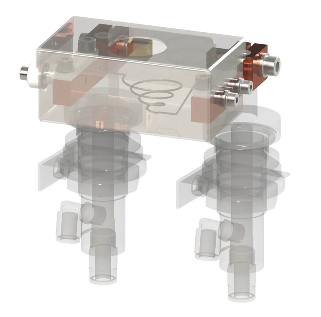
Figure 1: Moorfield TE1 thermal evaporation component with box-shielding (translucent here for showing internal parts).
The copper power legs can be seen mounted to water-cooled feedthroughs (bottom). The source supporting the evaporant is clamped between the power legs.
During operation, electrical current passes through the supply rods and into the source. The electrical properties of the source allow for resistive heating to high temperatures (depending on the source type), which, in turn, heats the supported evaporant. Under these conditions, the evaporant will melt and evaporate (or sublime) releasing vapour that moves up through the chamber vacuum to coat a substrate.
Types of thermal evaporation sources
Thermal evaporation is suitable for depositing a wide variety of materials. To a large extent, the capability of the technique is subject to the type of source fitted. Sources are typically fabricated from tungsten, tantalum or molybdenum, and come in several different forms, e.g., boats, baskets (including those suitable for supporting crucibles), filaments and coated rods. Some of these are shown in Figure 2, and described below.
Boats
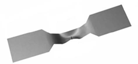
These are a common choice and come in a variety of sizes. In general, for the same evaporant, larger boats require higher powers for the same deposition rate and allow for greater maximum deposition rates.
Alumina coated boats can be used for evaporants that exhibit high adhesion to source materials, providing a surface that resists wetting. It should be noted however that these boats require a higher current to achieve similar temperatures. This type is often preferred for valuable materials.
Baskets
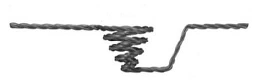
Are ideal if the user is less concerned with material losses versus using a boat. Baskets also allow for higher deposition rates with the same current due to generally high source voltages. Material is emitted in all directions from a basket; box shielding can be used to contain stray deposition. Baskets can be fitted with crucibles, often used for precious metals (retsricts wastage) or where a large volume of evaporant needs to be supported.
Rods
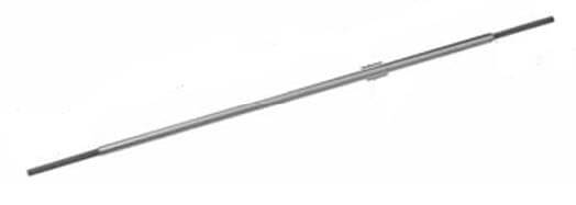
Are useful in situations where thermal evaporation is not possible using the forms detailed above, due to high evaporation temperatures that would require very-high currents for boat/basket sources not available using standard power supplies. For example, for chromium, it is common to use Cr-coated rods that allow for high temperatures using relatively low currents.
Important: It is critical that the correct source is used given the nature of the evaporant and power network onboard the tool. In this respect, key considerations are detailed below.
Temperature requirement
Firstly, we need to understand what temperature we need to heat a material to in order to release its vapour. As the process will be carried out under vacuum conditions, this is not the same as the evaporation/sublimation temperature at ambient conditions (e.g., the boiling point of gold under standard conditions is 2,700 °C, but we only need to achieve ~950 °C to release Au vapour at 5×10⁻⁶ mbar). Tables of required temperatures for various materials are widely available.
Power supply network
Power supply networks used for thermal evaporation are commonly rated by power, but the maximum output voltage and current are, in fact, more informative when choosing a source.
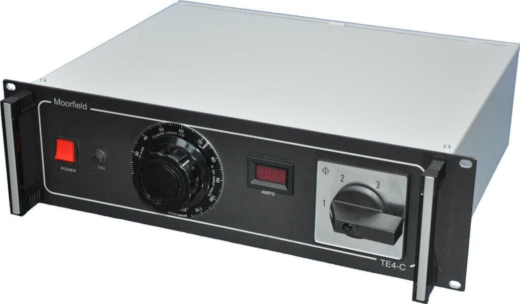
Figure 3: Rack-mount 4-channel manual control power supply network for thermal evaporation.
As an example, consider a tool fitted with an 800 W power supply network, with maximum voltage 8 V and maximum current 100 A. If we were to base our choice of source on the power alone, then numerous different models may seem appropriate. However, it would be quite easy to select a source with a correct power rating, but incorrect voltage and current. As an example, we might select a source with these properties: Power 342 W; voltage: 2.48 V; current: 138 A; temperature: 1,800 °C.
The maximum temperature here allows for deposition of many TE evaporants. However, the voltage and current indicate that we are unlikely to ever reach this temperature using the power supply network detailed above. On starting the supply and increasing the voltage, the current will increase. However, we only have 100 A available, and so once this is reached no more power will be delivered, even though the source could accept another 38 A (required for 1,800 °C operation). As such, a sizeable portion of the source’s power capability is not available with this setup.
Instead, it is important to match source voltage and current ratings to the maximum output of each available from the power supply network. If this is done correctly, then, as the power supply network approaches its maximum current output, the output voltage will also be close to the source’s voltage rating. As such, it will be possible to achieve close to the maximum possible power (and temperature).
Common issues with thermal evaporation:
Boat cracking
This can happen due to alloying between the boat and evaporant materials at evaporation temperatures. Once cracked, a boat must be discarded. This issue may be unavoidable for some evaporant/boat combinations, but the number of runs can be increased by avoiding thermal shock (see below).
Thermal shock
Rapid heating and cooling can cause boats to crack. To avoid this, power to the source should always be ramped up and down to ensure smooth and uniform heating.
Unwanted coating
As above, when using basket sources, material will be deposited in all directions, coating not just the substrate but also other surfaces with direct line-of-sight. This stray deposition can be restricted (for stopping coating of other in-chamber surfaces, e.g., chamber walls) using sources fitted with shielding—as present in Moorfield TE1 components. Once shielding is coated with enough material for flaking to occur, it can, with care, be removed for reuse.
Radiative losses
Although TE sources operate in high-vacuum environments (minimising convection), the high temperatures involved mean that much heat is lost through emitted IR. These losses can mean that sources struggle to reach their rated temperatures, even when operating at their maximum rated currents. Intelligent design of heat shielding can counter this.
Source length
Sources arrive with a set length, commonly 3.5” or 4” for those used for R&D purposes. This may be too long for a system’s sources and so cutting down will be required, which can be carried out using tin snips. Once cut, a DVM should be used to ensure electrical continuity has been preserved before installation within the source assembly.
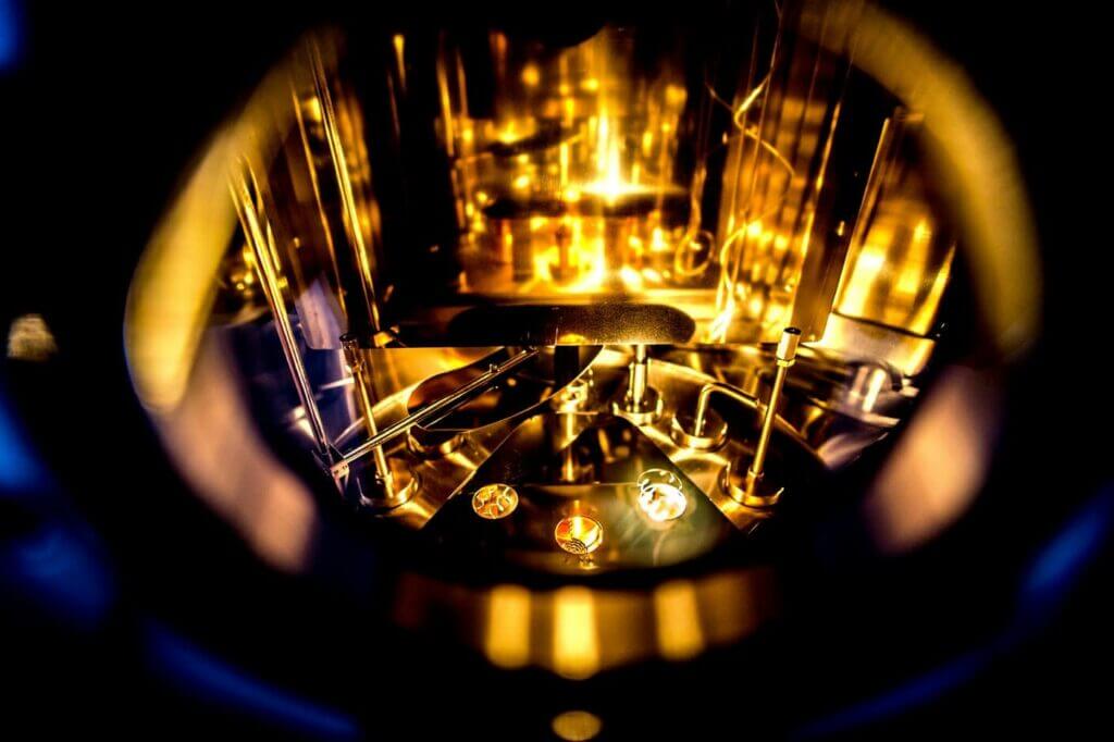 Figure 4: Thermal evaporation sources, fitted with filament sources, operating at high temperature inside a MiniLab 070 tool.
Further information
Moorfield design and assemble high-quality physical vapour deposition systems and components (including thermal evaporation) for R&D and industrial applications. For more information or to discuss your project, get in touch with our team.
Request more information