Load locks, or fast entry locks as they are sometimes called, are anti-chambers primarily designed to reduce the process chamber cycle time, hence increase the number of deposition runs per unit of time.
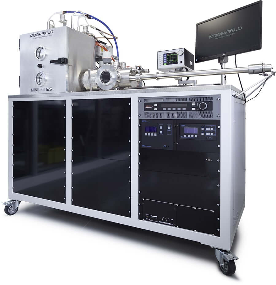
Real-world applications of Moorfield products in science
Load lock and fast entry chamber options

The load lock is designed such that it has low volume relative to the substrate size and, together with a carefully selected pumping group, the pump down time is very quick (circa 5×10⁻⁶ mb in 10 minutes). This allows for fast sample transfer into and out of the process chamber. This is the major cost driver during the decision process when configuring a deposition system.
However, there are many other advantages which, when considered together make a load lock a very sensible and often necessary upgrade to a system. With a load lock fitted to the system, the process chamber is only vented for routine maintenance (target changes etc.) hence the base pressure is circa an order of magnitude better than a cycled chamber. This results in a higher quality film as the oxygen partial pressure is lower.
When additional pre or post processes are added to the load lock, the functionality of the system increases as does the film quality. For example, etching a substrate inside the load lock prior to deposition eliminates possible oxidation when moving from a dedicated RIE system into the process chamber via atmosphere. It is also better than process chamber etch as the removed debris is contained in the load lock chamber thus does not thermally migrate during deposition.
End station linear load locks:
This standard load lock has a single axis of transfer along the length of the load lock chamber. A turbo pump is positioned horizontally and facing the entry door whilst a gate valve (manual or pneumatic) separates the load lock from the process chamber.
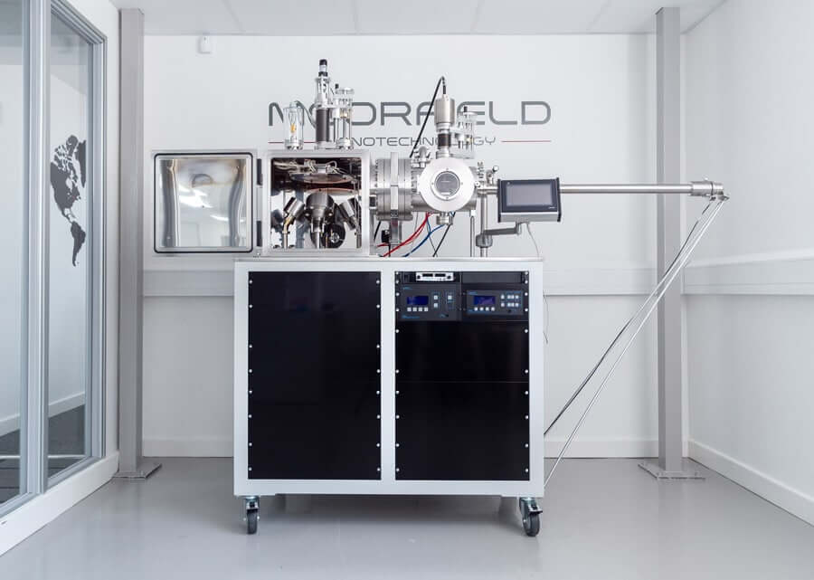
Image: Example of an end station linear load lock fitted to a Moorfield MiniLab 060
A magnetically coupled linear transporter probe carries the substrate on a platen through the gate valve and into the process chamber where the platen is “handed off” to the process chamber substrate stage. All Moorfield integrated load locks are supplied with semi-automated transfer and interlocks for pressure, gate valve and probe arm positioning
Mid station linear load locks:
Designed to be shared between two in-line systems, the mid-station load lock has a single axis of transfer along the length of the load lock chamber. A turbo pump is positioned vertically from below and the entry door port vertically about the central position.
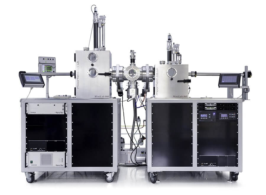
Image: A MiniLab 080 and MiniLab 060 connected via a mid station linear load lock
Two gate valves (manual or pneumatic) separate the load lock from the process chambers. Two magnetically coupled linear transporter probes, sited on the adjacent process chamber side walls, carry the substrates on a platen through the gate valve and into the load lock chamber where the platen is “handed off” to a rotation/Z-shift stage.
All Moorfield integrated load locks are supplied with semi-automated transfer and interlocks for pressure, gate valve and probe arm positioning.
Options for load lock systems:
Parking stage
Designed to allow a substrate platen to be parked inside the load lock prior to deposition.
Annealing station
Various temperature and gas admission options allows for pre and post heating of the substrate in controlled atmospheres.
RIE station
An RF plasma station with option to etch in standard form (circa 1W/Cm2) or “soft etch” for 2D materials in hi-res RF form. Optional gas packages and pressure control sub- systems available with the RIE station.
Z-shift
In situ Z-shift (motorised or manual) is required on some load lock modules.
Parking cassette and elevator
Allows multiple substrate platen or shadow mask stacking where the process requires in vacuum mask / substrate exchange. In situ Z-shift (motorised or manual) is required with this module.
Gate valves
All Moorfield Load locks specify CF flanged gate valves. Size range from NW63CF to NW200CF. Manual or pneumatically actuated. Pneumatic relay valves and position indicator options.
Gauging
Wide range gauge Atmosphere to 10-8mb.
Gas Cooling Station
Allows Insitu platen temperature to be monitored whilst gas is injected directly below the platen
Substrate platens
2” to 8” single substrate platens in SS304, SS316, Inkonel, Ceramic, graphite or Molybdenum. Customised multiple substrate platens.
Gas introduction sub-systems
Needle valve manual gas admission systems. Up to 4 channel Mass Flow Control valves. Turbo Throttle valves and capacitance manometer gauge options.
Pumping groups
Edwards turbomolecular vacuum pumping group: nXDS6i/nEXT85i; nXDS10i/ nEXT255i.
System requirements:
- Process gases: 25 psi supplies, 99.99% purity or better
- Service gas: Dry compressed air, nitrogen or argon, 60–80 psi supply
- Vent gas: N2, 5 psi
- Power: Single-phase 230 V, 50 Hz, 13 A
- Chilled water: 18–20 °C, 3 L/min, pressure < 4 bar
- Exhaust extraction
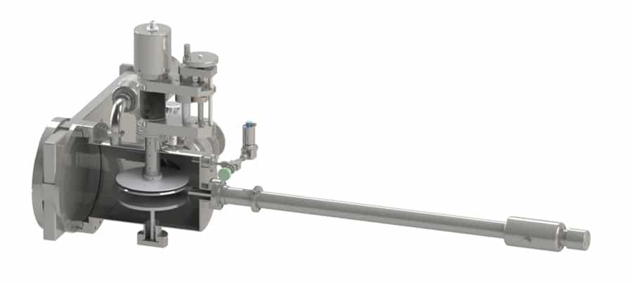
Image: Example etch load lock (rear cutaway)
Key benefits of load lock systems:
- Increases tool productivity
- Reduces process chamber vent cycles
- Reduces process chamber turbo pump wear
- Increases film quality
- Allows for offline processes ( etch, anneal etc)
- Single or multiple substrate pass options